Field Service · Technical Blog — A complete, illustrated guide distilled from the official Riotouch RK3588 Interactive Flat Panel service manual (English version): system architecture, power supplies, connector pinouts, disassembly & repair, firmware update and troubleshooting. Audience: service engineers, repair technicians & AV support teams · Figures: from the manual, for reference only
1. What this manual covers
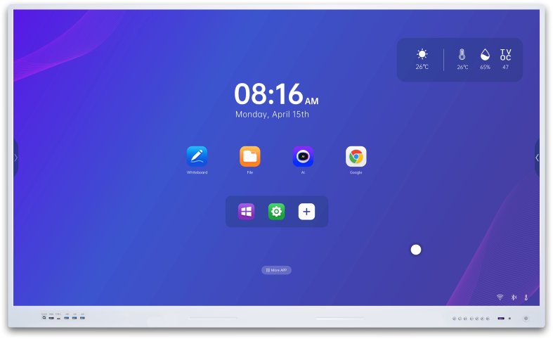
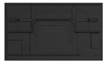
The Riotouch RK3588 Interactive Flat Panel (IFPD) is a large-format touch display built around the Rockchip RK3588 application processor. It is sold as a conference-room whiteboard / smart display, and — depending on the panel size — ships with one of three power supply boards:
The service manual walks a technician through everything needed to repair the unit in the field: the block diagram of the RK3588 electrical system, the power architecture with socket pin definitions, every external port and every internal connector on the main board, the advanced pinouts used during board-level service, the disassembly procedure for the rear shell and the boards behind it, the factory menu and firmware update procedures (USB and OTA), and finally a set of troubleshooting decision charts for the most common faults (no display, no OPS signal, no audio, no touch).
2. Safety instructions
Before any work, read the safety instructions carefully to avoid dangers during use:
3. System architecture (RK3588)

The machine is organized as a small set of replaceable electronic blocks:
This modular split is what makes field service practical: most failures can be isolated to one board (power board, main board, OPS adapter board, LCD/T-CON, or the key/IR and touch assemblies) and repaired by replacement.
4. Power supply boards
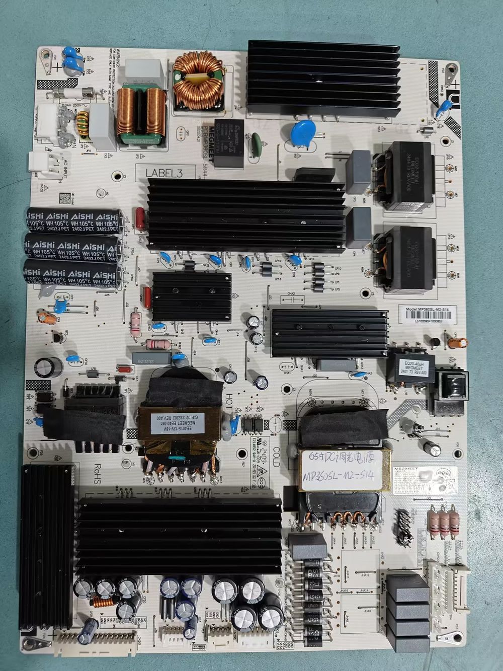
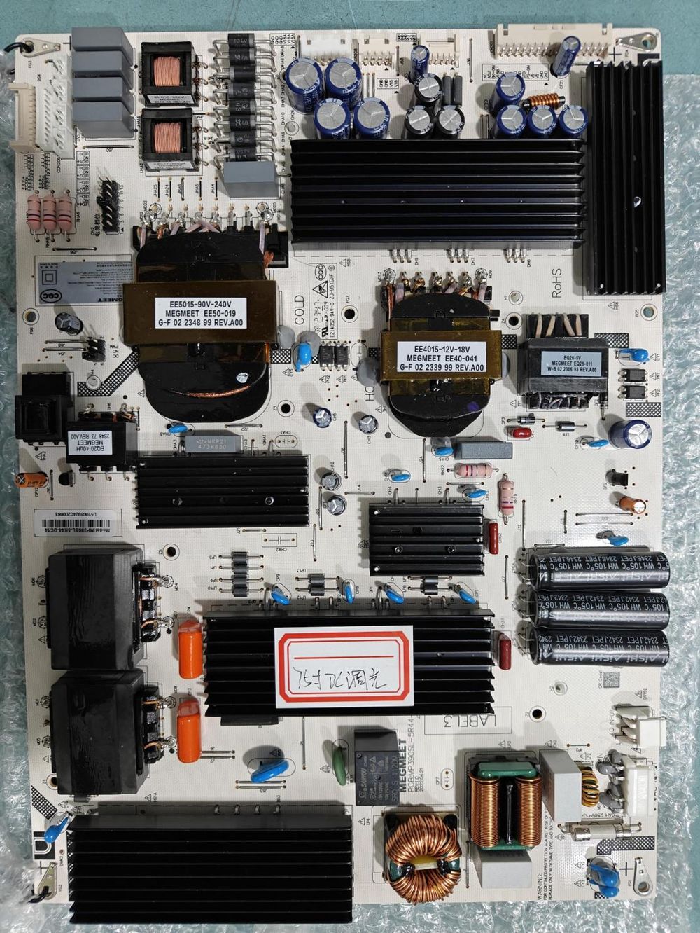
All three power boards are multi-output switch-mode supplies delivering the same voltage rails — +5.2VSB (standby), +5V, +12V and +18V — with short-circuit, over-current and over-voltage protection circuits. They differ in total output power according to panel size:
| Panel size | Power board | Total output |
|---|---|---|
| 65″ | MP360SL-M2-S14 | 360 W |
| 75″ | MP390SL-5R44-DC14 | 390 W |
| 86″ | MP550SM-5S34-ADC | 500 W |
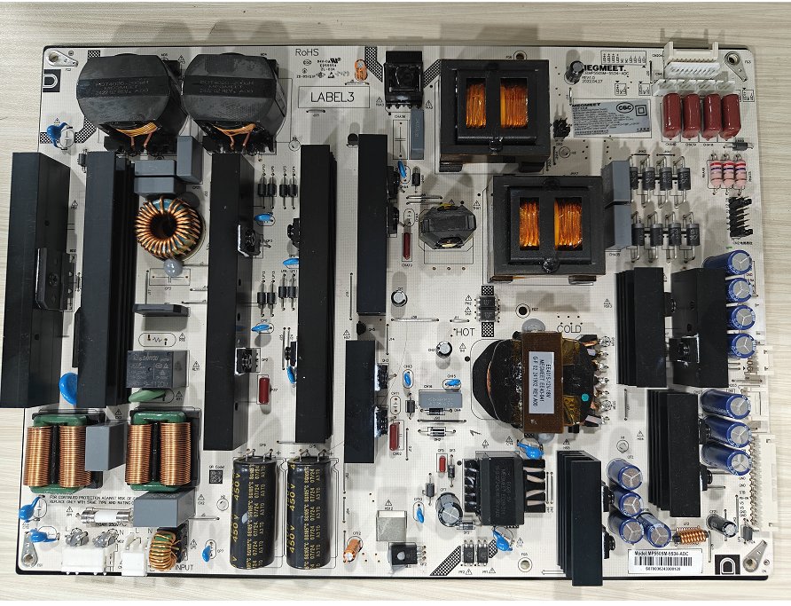
86″ MP550SM-5S34-ADC (500 W)
4.1 Power-board socket pin definitions
CN101 — AC mains input (5-pin or 3-pin, pitch 3.96 mm)
| Pin | Signal | Function |
|---|---|---|
| 1, 2 | L | AC input line (live) |
| 4, 5 | N | AC input neutral |
CN201 — main power/control connector (15-pin, pitch 2.5 mm)
| Pin | Signal | Function |
|---|---|---|
| 1, 2, 7, 8, 11 | GND | Return for STB / V5 / V12 / V18B |
| 3, 4 | V5 | +5 V DC output channel |
| 5 | PS-ON | SMPS on/off control signal input |
| 6 | STB | Standby (+5.2 VSB) channel DC output |
| 9, 10 | V12 | +12 V DC output channel |
| 12 | V18B | +18 V DC output channel |
| 13 | BK | Backlight control signal input |
| 14 | ADJ | Backlight brightness adjust signal input |
| 15 | PC-ON | PC (OPS) on signal input |
Board-to-board power rails
| Connector | Pitch | Pins & signal | Function |
|---|---|---|---|
| CN203 (6-pin) | 2.0 mm | 1, 2, 3 = V12 · 4, 5, 6 = GND | +12 V feed to loads |
| CN202 (6-pin) | 2.5 mm | 1, 2, 3 = V18A · 4, 5, 6 = GND | +18 V feed (rail A) |
| CN208 (4-pin) | 2.5 mm | 1, 2 = V18A · 3, 4 = GND | +18 V feed (rail A) |
LED backlight channel connectors
| Connector | Pitch | LED− return | NC | LED+ outputs |
|---|---|---|---|---|
| CN204 (10-pin) | 2.0 mm | pins 1–4 | 5, 6 | 7–10: LED1+ … LED4+ |
| CN4 (10-pin) | 2.0 mm | pins 1–4 | 5, 6 | 7=LED4+ · 8=LED3+ · 9=LED2+ · 10=LED1+ |
| CON208 (3-pin) | 2.0 mm | pin 1 | 2 | 3 = LED4+ |
| CON209 (3-pin) | 2.0 mm | pin 1 | 2 | 3 = LED3+ |
| CON210 (3-pin) | 2.0 mm | pin 1 | 2 | 3 = LED2+ |
| CON211 (3-pin) | 2.0 mm | pin 1 | 2 | 3 = LED1+ |
5. External ports
All user-facing ports live on the rear of the unit. The manual numbers them and defines each port's type and direction:
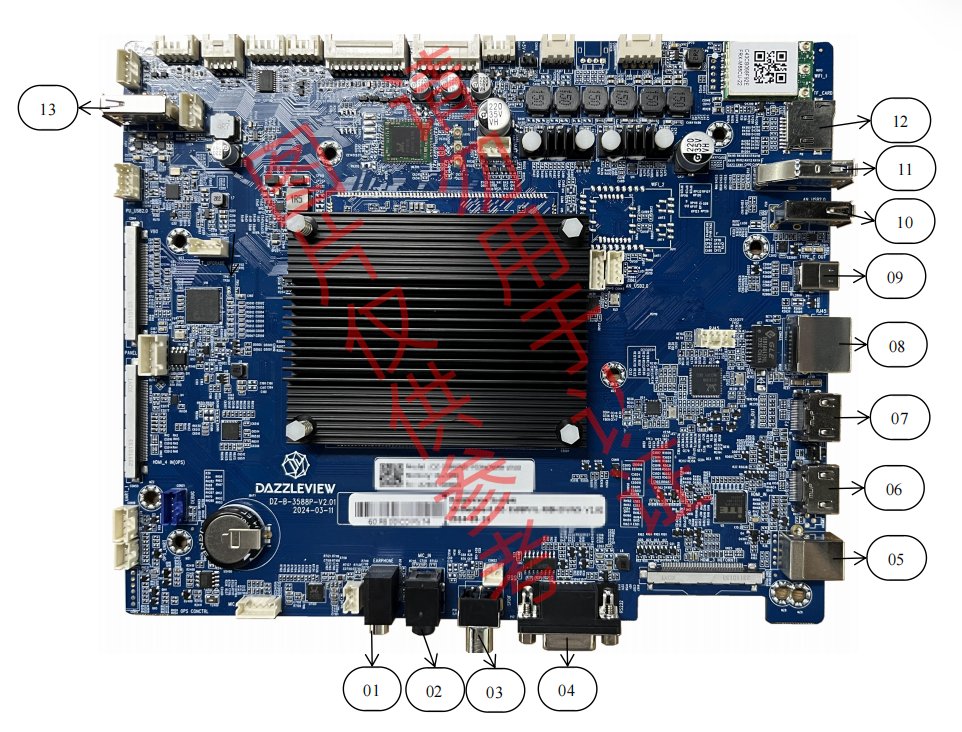
| # | Connector | Type | Direction |
|---|---|---|---|
| 1 | Earphone | Earphone jack | Output |
| 2 | MIC IN | Earphone jack | Input |
| 3 | SPDIF OUT | Standard (coaxial optical) | Output |
| 4 | RS232 | DB9 | In / Out |
| 5 | Touch USB | USB 2.0 Type-B | In / Out |
| 6 | HDMI IN (HDMI) | HDMI | Input |
| 7 | HDMI OUT | HDMI | Output |
| 8 | RJ45 | Standard Ethernet | Input |
| 9 | TYPE-C OUT | Standard USB-C | Output |
| 10 | Android USB 2.0 | USB 2.0 Type-A | In / Out |
| 11 | Android USB 3.0 | USB 3.0 Type-A | In / Out |
| 12 | TF CARD | microSD slot | In / Out |
| 13 | TP_USB | USB 3.0 Type-A | In / Out |
6. Internal connectors on the main board
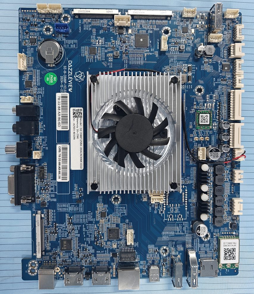
With the back cover removed, all internal board connectors are accessible. The manual provides a numbered map of the main board with a location table:
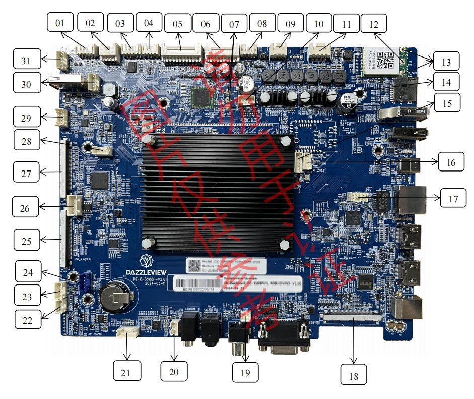
| # | Location | Function | # | Location | Function |
|---|---|---|---|---|---|
| 1 | CON24 | NFC | 16 | CON45 | Android USB 2.0 |
| 2 | CON27 | GPIO | 17 | CON8 | RJ45 |
| 3 | CON3 | MCU upgrade | 18 | / | Front HDMI |
| 4 | CON23 | MCU UART | 19 | CON22 | SPDIF OUT |
| 5 | CON16 | Key & IR & ADC | 20 | CON7 | Earphone |
| 6 | CON1 | Power | 21 | CON13 | MIC IN |
| 7 | ANT6 / ANT7 | Wi-Fi antenna | 22 | CON26 | OPS UART |
| 8 | CON53 | 5 V power | 23 | CON18 | UART 1 |
| 9 | CON15 | Subwoofer | 24 | CON21 | Debug |
| 10 | CON20 | UART 6 | 25 | CON50 | OPS |
| 11 | CON14 | Speaker | 26 | CON4 | 51-pin V-By-One (8-bit) |
| 12 | / | Bluetooth antenna | 27 | CON52 | LT upgrade |
| 13 | / | Hot-spot antenna | 28 | CON51 | Full-source-sharing USB 2.0 |
| 14 | ANT8 | Bluetooth antenna | 29 | CON44 | TP USB |
| 15 | CON40 | Wi-Fi USB 2.0 | 30 | CON17 | TP UART |
Three different “service” busses deserve attention before they are needed:
7. Interface definitions & pinouts (for advanced service)
This section of the manual is aimed at board-level work.
7.1 CON1 — power & backlight (2×9-pin, pitch 2.0 mm)
The main power-and-backlight header from the power board to the RK3588 main board:
| Pin | Function | Pin | Function |
|---|---|---|---|
| 1 | Standby on/off (GPIO out, up to 5 V) | 2 | 5VS |
| 3 | GND | 4 | GND |
| 5 | ADJ (backlight adjust) | 6 | ON/OFF |
| 7 | GND | 8 | GND |
| 9 | +5 V | 10 | +5 V |
| 11 | GND | 12 | GND |
| 13 | +12 V | 14 | +12 V |
| 15 | GND | 16 | GND |
| 17 | AMP_VCC | 18 | AMP_VCC |
7.2 CON40 — keys, IR receiver & ADC (2×11-pin, pitch 2.0 mm)
Connects the front keypad/IR board (referred to as CON16 in the connector map of §6):
| Pin | Function | Pin | Function |
|---|---|---|---|
| 1 | GND | 2 | GND |
| 3 | K7 | 4 | LED_R |
| 5 | K6 | 6 | LED_G |
| 7 | K5 | 8 | IR |
| 9 | K4 | 10 | IR_VCC |
| 11 | K3 | 12 | ADC |
| 13 | K2 | 14 | SDA |
| 15 | K1 | 16 | SCL |
| 17 | K0 | 18 | +3.3 V |
| 19 | GND | 20 | GND |
| 21 | LED+ | 22 | LED− |
K0–K7 are the front-panel key scan lines, the IR receiver is fed by IR_VCC, and an I²C bus (SDA/SCL) plus an ADC input are available for auxiliary boards.
7.3 VBO — 51-pin V-By-One panel interface (60 Hz VB1, 8-bit)
The RK3588 main board talks to the T-CON board over V-By-One (header CON4):
| Pin(s) | Signal | Function |
|---|---|---|
| 1–24 | VBY7P/N … VBY0P/N | 8 V-By-One differential data lanes (P/N pairs separated by GND) |
| 25 | GND | Ground |
| 26 | VBYLOCKN | V-By-One lock signal (active low) |
| 27 | VBYHTPDN | Hot-plug / power-down control |
| 28–32, 35, 38, 43, 44 | NC | Not connected (reserved) |
| 33, 34 | V_SCL / V_SDA | DDC I²C bus to the panel |
| 36, 37 | DATA_FORMAT_1 / DATA_FORMAT_0 | Data-format / link-config straps |
| 39–42 | GND | Ground |
| 45–51 | VCC_PANEL | Panel power feed (V-By-One + T-CON supply) |
7.4 CON14 — speakers (4-pin, pitch 2.54 mm)
| Pin | Signal | Meaning |
|---|---|---|
| 1 | AMP_L+ | Left channel + |
| 2 | AMP_L− | Left channel − |
| 3 | AMP_R− | Right channel − |
| 4 | AMP_R+ | Right channel + |
7.5 Pinout diagrams for the remaining internal connectors
The manual gives a pinout picture for each internal service connector. Diagrams below follow §5 of the manual:
| Connector | Function | Pinout |
|---|---|---|
| CON24 | NFC module (5-pin / 2.0 mm) | 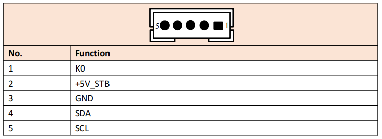 |
| CON27 | GPIO (2×4-pin / 2.0 mm) | 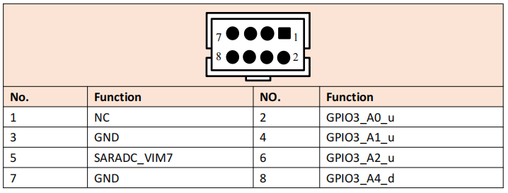 |
| CON3 | MCU upgrade (5-pin / 2.0 mm) | 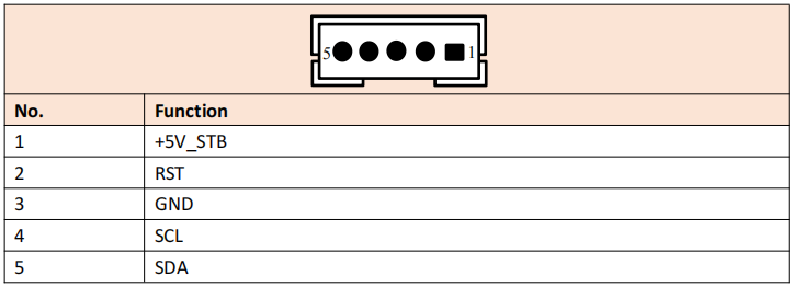 |
| CON23 | MCU UART (4-pin / 2.0 mm) | 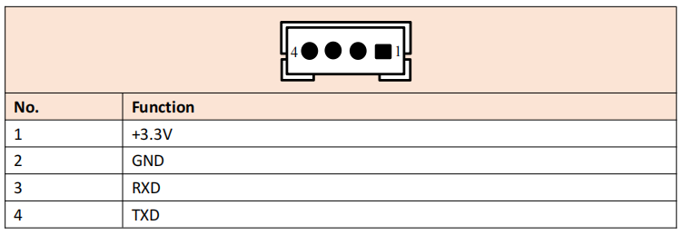 |
| CON53 | 5 V power (4-pin / 2.0 mm) | 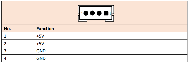 |
| CON20 | UART 6 (4-pin / 2.0 mm) | 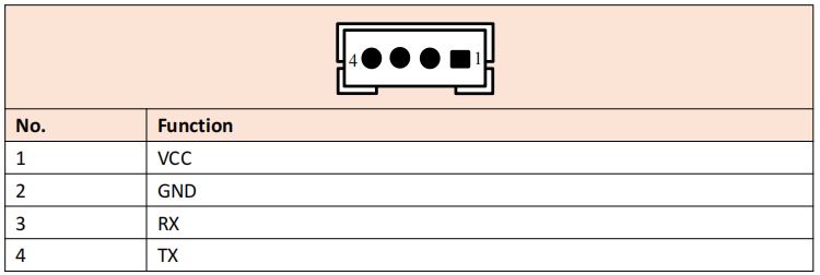 |
| CON45 | Android USB 2.0 (2-pin / 2.0 mm) | 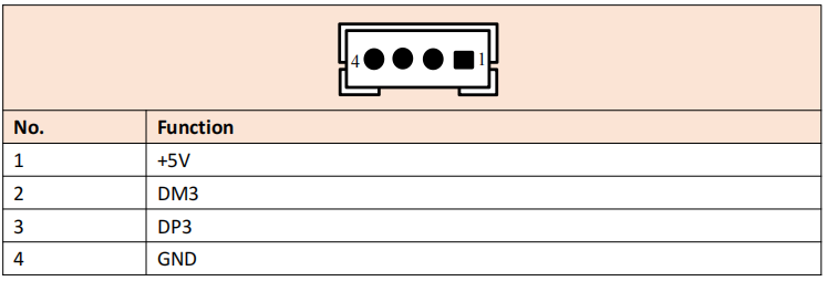 |
| CON40 | Wi-Fi USB 2.0 (5-pin / 2.0 mm) | 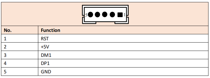 |
| CON22 | SPDIF out (2-pin / 2.0 mm) | 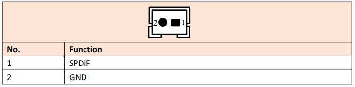 |
| CON7 | Earphone (3-pin / 2.0 mm) | 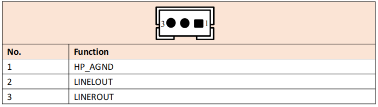 |
| CON13 | MIC in (5-pin / 2.0 mm) | 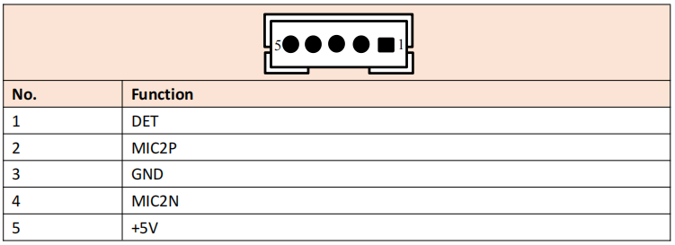 |
| CON26 | OPS UART (3-pin / 2.0 mm) | 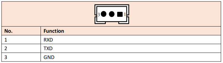 |
| CON18 | UART 1 (4-pin / 2.0 mm) | 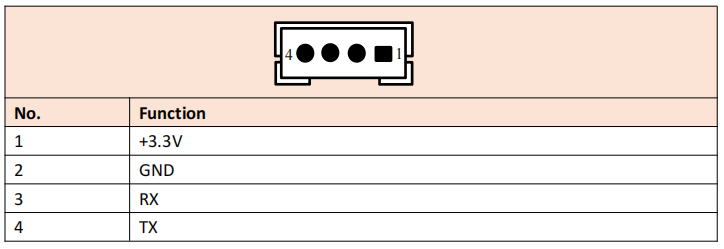 |
| CON44 | TP USB (4-pin / 2.0 mm) | 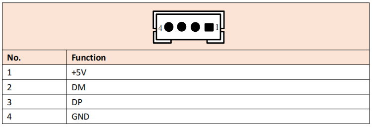 |
| CON17 | TP UART (4-pin / 2.0 mm) | 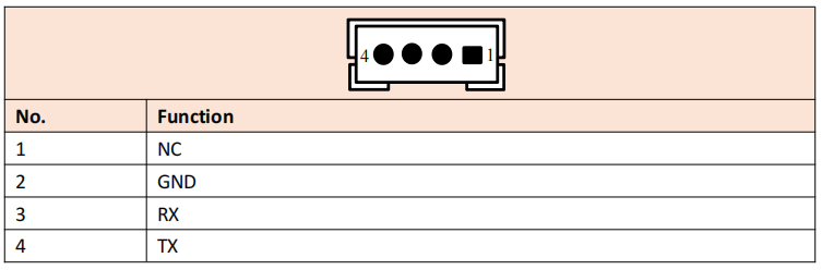 |
| CON51 | Full-source-sharing USB 2.0 (2×4-pin / 2.0 mm) | 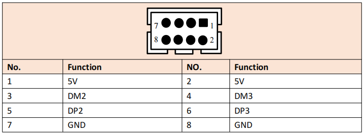 |
| CON8 | RJ45 (2×4-pin / 2.0 mm) | 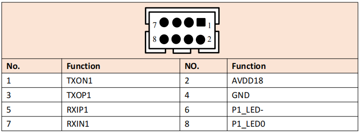 |
| CON15 | Subwoofer (3-pin / 2.5 mm) | 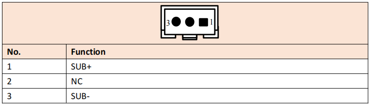 |
| CON21 | Debug (4-pin / 2.0 mm) | 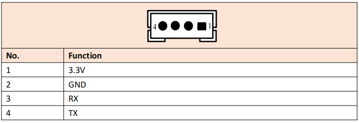 |
8. Maintenance & disassembly
8.1 Tools
Phillips screwdrivers, needle-nosed pliers, slotted screwdrivers and tweezers. The needle-nosed pliers and slotted screwdrivers are specifically recommended to guard against screw slips and detached hex copper posts — a common field accident when screws are seized or cross-threaded.
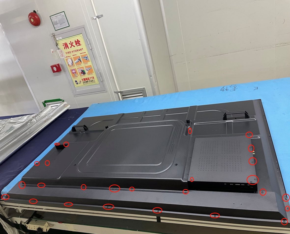
8.2 Step 1 — Removing the back shell
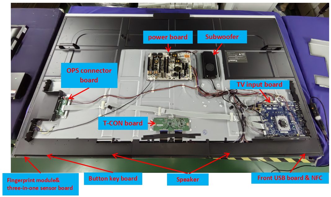
Once the back shell is off you can reach the power board, main board, OPS adapter board and the internal cabling. Replacing the speakers, the keypad PCB, the IR receiver board, the front interface board or the infrared touch frame additionally requires removing the lower rear case.
8.3 Step 2 — Replacing the power board / main board
8.4 Attention notices for disassembly
9. Software: factory menu & firmware update
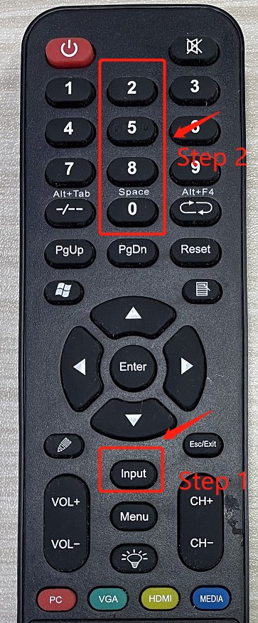
9.1 Entering the factory menu
What you can do inside the factory menu:
9.2 Firmware update — two modes
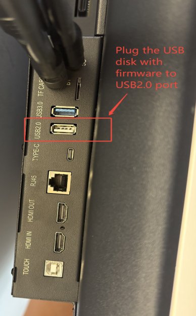
9.2.1 Upgrade via USB disk
9.2.2 Upgrade via OTA
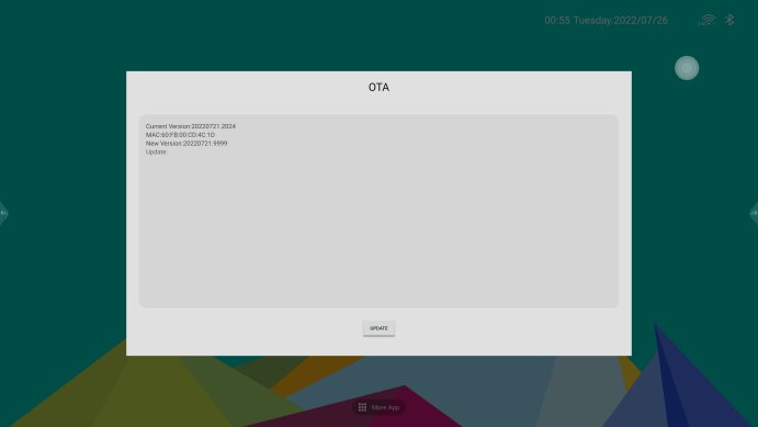
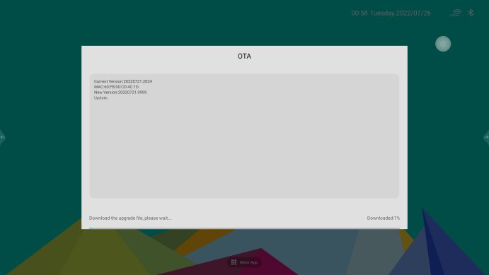
10. Troubleshooting flow
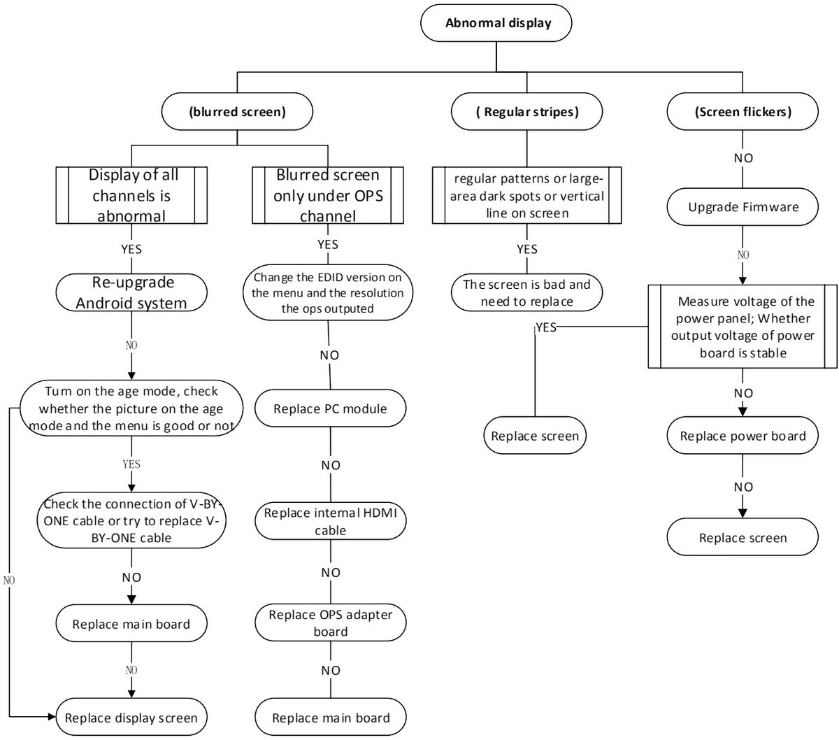
The last chapter of the manual is a set of decision charts for the most common complaints. The logic is summarized below as compact service paths — follow the probe questions in order and stop at the first action that fixes the fault.
10.1 Abnormal display
10.2 No image (black screen)
Q1. Can the display be turned on by the remote control / key controller?
Q2. Power LED is green but there is no image
10.3 OPS no signal (OPS cannot start)
10.4 No audio
10.5 No touch
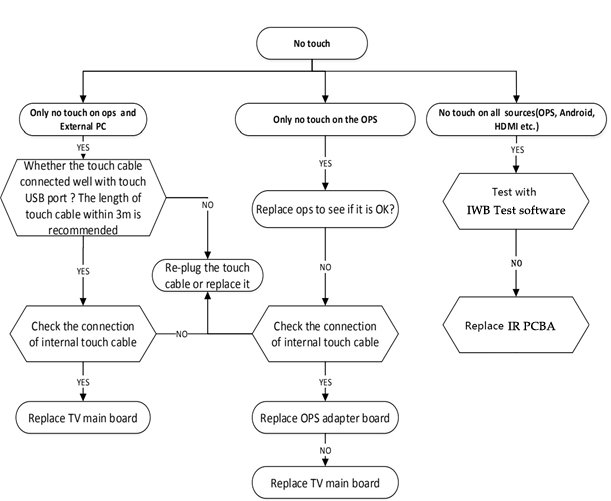
Touch quick checks from the manual map. The touch controller connects through TP USB (CON44) and TP UART (CON17), the touch frame through the Touch USB (Type-B) port on the rear panel (§5). For “no touch” complaints, verify the USB enumeration and those cables before suspecting the touch frame itself.
Wrap-up
The Riotouch RK3588 IFPD is a genuinely service-friendly design: a clear RK3588 electrical architecture, standardized multi-output power boards selected by panel size, fully documented port and connector maps, and pinouts for every internal header. With the disassembly steps and the fault-isolation flows above, a technician can confidently replace the power board, main board, OPS adapter board, speakers, or the touch/IR assemblies in the field — and the USB/OTA firmware paths keep the software side under control.
Source: Riotouch RK3588 Interactive Flat Panel service manual (English version) — this article is a distilled, editorial walkthrough of that manual for service and documentation purposes. All product names, figures and photographs remain the property of their respective owners. Figures are reproduced for reference only and are subject to the actual product. Unauthorized disassembly may void the warranty — always follow the manual and the local service guidelines.
- 65-inch version — MP360SL-M2-S14 power board (360 W)
- 75-inch version — MP390SL-5R44-DC14 power board (390 W)
- 86-inch version — MP550SM-5S34-ADC power board (500 W)
- Do not expose the machine to rain or moisture and direct sunlight.
- Do not let any liquid substance seep inside the machine.
- Do not place the LCD display near a heat source, such as a heater.
- After using the display, disconnect the power supply.
- Do not touch the body with live operation and corrosive liquids when cleaning the display.
- When using the plug, be careful not to push it into the port forcibly — make sure there is no debris in the port, the plug matches the port, and the orientation is correct.
- Heat is dissipated through the air inlet and outlet on the back side. Never cover the machine and always keep the ventilation openings clear.
- RK3588 main board — the core of the unit: controls all input and output port signals, decodes the incoming audio/video signals, and sends V-By-One signals to the T-CON board to drive the LCD panel.
- LCD module — displays the image (driven by the T-CON).
- Power switch (ON/OFF) — the machine's main power switch.
- Remote-control keypad — receives remote-control and front-key commands and passes them to the main board.
- OPS adapter board — adapts the OPS module interface to HDMI, USB and power interfaces on the main board.
- MCU upgrade (
CON3) and MCU UART (CON23) — used to program or debug the on-board microcontroller (e.g., after a key/IR or power-management fault). - Debug (
CON21), UART 1 (CON18) and UART 6 (CON20) — serial debug consoles for the Android side and the OPS path. - LT upgrade (
CON52) — the touch / T-CON upgrade header; and TP USB (CON44) / TP UART (CON17) connect the touch controller.
- Place the machine on a table with foam or a mat underneath so the tempered glass never takes direct stress.
- Screw spec for the 65″ example: TX M3×6 mm countersunk (“meson head”), nickel plated — torque 5 ± 1 kgf·cm.
- Unscrew the screws marked with red circles to take off the two back covers (the large back cover and the lower back cover).
- Photograph the original wiring first. If you are not sure about the interfaces on the board, a picture prevents inserting a cable into the wrong header.
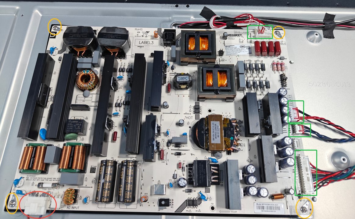
- Board screws: M3×6 mm pan head with elastic pad + flat pad, blue-zinc-plated machine screws ×4 pcs, torque 5 ± 1 kgf·cm.
- Work through the internal cable connectors in the numbered order shown in the manual so the boards lift out cleanly.
- Electricity safety. Do not touch any electronic boards or cables before cutting off the power cable.
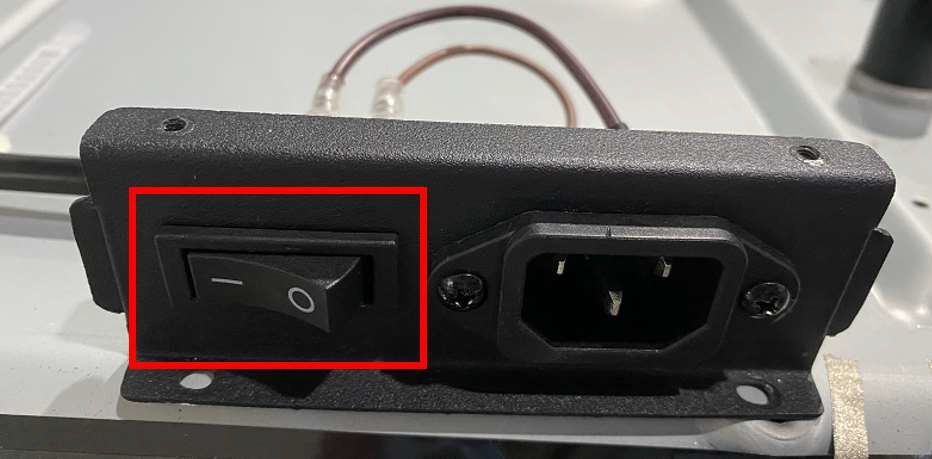
Disconnect the power cable before touching any electronic board or cable. - Check the power cables are wrapped by acetate tape — re-wrap them on re-assembly.
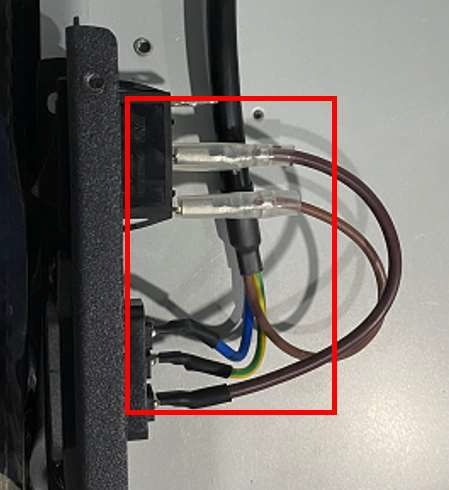
Power cables wrapped with acetate tape — re-wrap them on re-assembly. - Take a photo of the original state of the cabling so you do not connect the wrong cables or miss a cable during re-assembly.
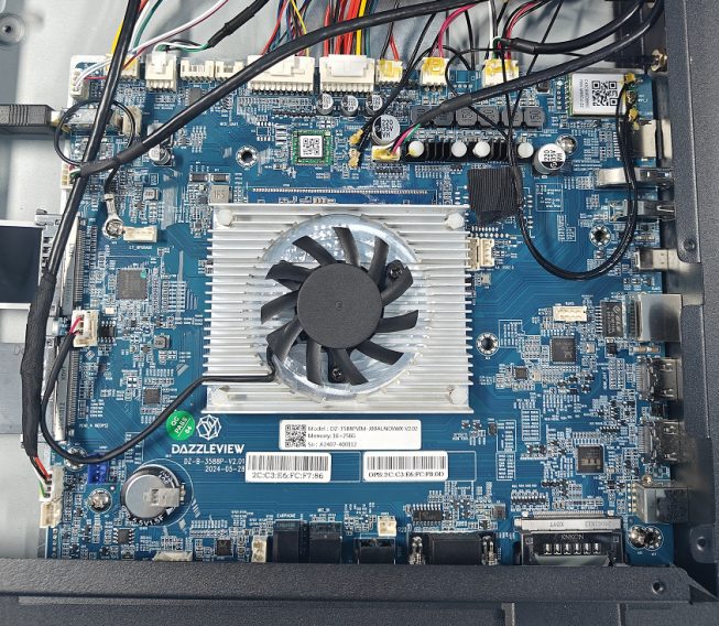
Take a photo of the original cabling state before disconnecting anything. - Remove the fixing glue first. Before pulling out wires, carefully remove the fixing glue on the surface of the connectors with a blade — otherwise the wires break easily.
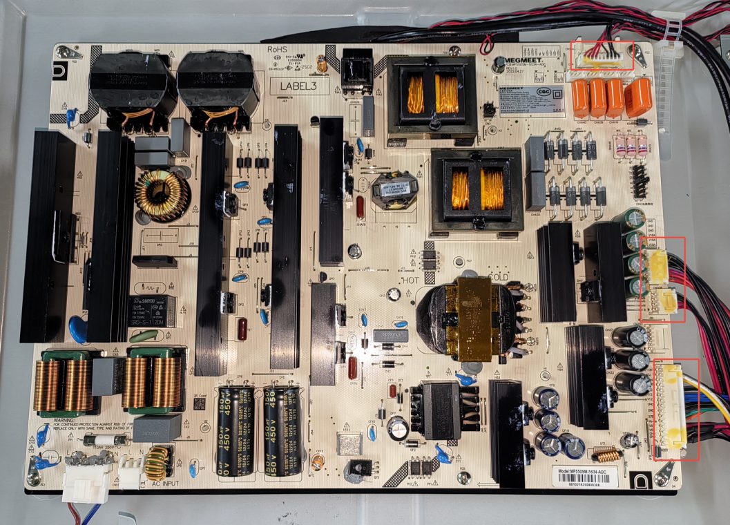
Carefully remove the fixing glue on the connector surface with a blade. 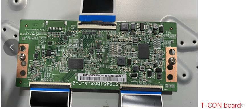
Fixing-glue detail — once the glue is removed the wires pull out cleanly instead of breaking. - Re-tighten screws diagonally. When fixing boards back, tighten the screws in a diagonal order to seat the board evenly.
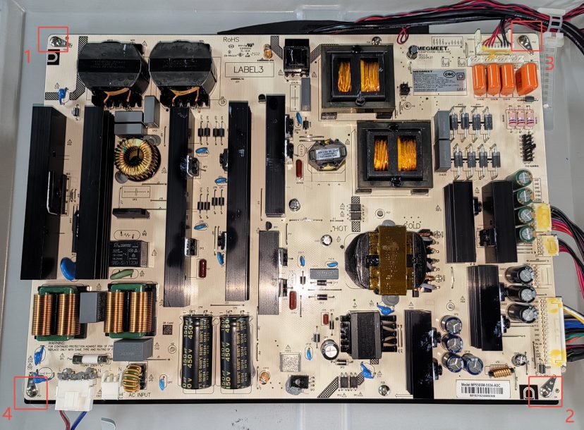
Re-tighten the board screws diagonally so the board seats evenly.
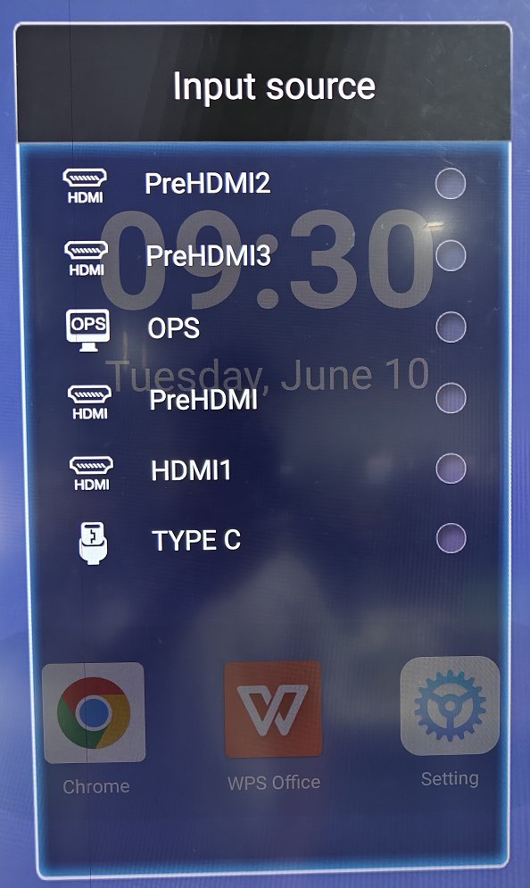
- Press INPUT on the remote control;
- then press the four numbers 2580 on the remote;
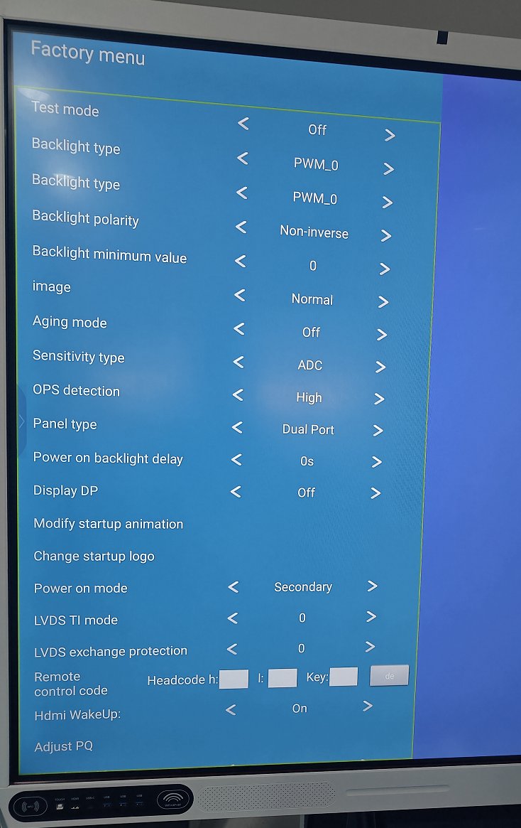
- the factory menu opens with Test mode, Backlight type, OPS detection, Panel type and Other Settings.
- Common Settings — motherboard status, power-on mode, panel settings, backlight polarity, backlight frequency, OPS status detection, upgrade boot logo, upgrade boot video, aging mode, etc.;
- Advanced Settings — picture adjust, voice adjust;
- Other Settings — reserved.
- Prepare a USB disk formatted as FAT32.
- Unzip the firmware package downloaded from the distributor (Google Drive / e-mail).
- Copy the firmware image
dz982P_upgrade_package.imgto the FAT32 USB disk. - Plug the USB disk into the rear Android USB 2.0 port (item 10 in §5 — do not use the USB 3.0 port).
- Turn the panel off.
- Long-press the power button for ~10 seconds — the update then runs by itself.
- At 100% the panel reboots — the first boot takes about 5–10 minutes, so be patient.
- Make the setting that puts the panel in the right mode (switch from dual to single display mode).
- Set the language.
- Send the unit's MAC address and software version to the manufacturer.
- The manufacturer releases the new firmware to your panels on the remote update server.
- On the panel, tap UPDATE to download the install package.
- No power at all — power indicator cannot be turned on:
- Swap the power cable and power outlet for a known-good pair. Fixed? Done.
- Ensure the power cable is connected to a good, known wall outlet.
- Check whether the power-board cables are seated well.
- Measure whether +5VSB is present on the corresponding pin of the TV power board.
- No 5VSB → replace the TV power board.
- Red power LED on but cannot turn green:
- Replace the KEY & IR board (startup keys / standby control).
- Still red → replace the TV main board and KEY & IR board together.
- Flashlight test: shine a flashlight on the screen — is a faint picture visible?
- Picture present → backlight failure:
- Re-plug and replace the V-By-One cable.
- If the T-CON board is replaceable, replace the T-CON.
- Otherwise replace the screen (LCD module).
- No picture at all → replace the TV main board.
- Picture present → backlight failure:
- Q1: Is the input on the OPS source? If not, switch to the OPS source.
- Q2: Does the OPS power light come on?
- Dark → press the OPS power key; if still dark, loosen the screws of the OPS rail, re-plug the OPS module, and finally replace the OPS module.
- Light but no picture → in order:
- Re-plug and replace the internal HDMI cable (OPS → main board).
- Replace the OPS adapter board.
- Replace the power board and the power cable to the OPS.
- Update the firmware.
- Replace the OPS adapter board / TV main board as the last steps.
- Q1: Is sound missing on all sources (OPS, Android, HDMI, VGA…) or only on the PC/OPS source?
- Only the OPS/PC source:
- Check the sound settings of the OPS source.
- Re-install the OPS audio driver or replace the OPS module.
- Replace the OPS adapter board → replace the TV main board.
- All sources:
- Check that the Android sound setting is normal.
- Check the connection of the internal speaker cable.
- Earphone test: plug an earphone into the earphone port — is there sound through the earphone?
- Earphone OK → the internal audio amp / speakers are the suspects: re-plug or replace the speaker cable, then replace the speakers.
- No sound through the earphone either → replace the TV main board.
- Only the OPS/PC source:
Related Product
Related Articles
Need a Solution That
Fits Your Project?
Tell us what you're looking for and we'll tailor a quote to your requirements — with pricing, lead time, and expert advice.